System Configuration of the Demonstration Facility
Demonstration facility Mechanisms and Specifications
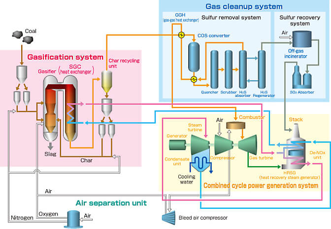
Gasification system
The gasifier is a pressure vessel with internal pressure maintained at 3 MPa (approx.) and fitted with a gasifier chamber surrounded by a water-cooled membrane wall.
The gasifier chamber is divided into two sections: a combustor and a reductor.
Gasification occurs following the introduction of pulverized coal and air from the burner.
Pulverized coal in the combustor is burned at approx. 1800 ℃ to generate the heat needed for the gasification reaction in the reductor and to enable the discharge of coal ash as molten slag.
The reductor is equipped with functions that initiate gasification when pulverized coal is introduced to the high-temperature gas arriving from the combustor located underneath it. These functions also decrease the temperature of the gas through an endothermic reaction accompanying gasification, thereby preventing the adhesion of ash in the SGC heat exchanger located downstream.
The gasifier is divided into two sections and is described as having a two-stage entrained flow gasification configuration, with the combustor at the bottom and the reductor at the top. The configuration facilitates the melting of ash at the high temperatures made possible by the intensive introduction of air into the combustor and by a mechanism that allows use of the reductor exclusively for gasification reactions to allow smooth gasification.
Of the pulverized coal supplied to the gasifier, powder (char) containing fixed carbon is caught by the char recycling unit and reintroduced to the gasifier. The char recycling unit consists of a cyclone separator and a porous filter.
Gas cleanup system
The gas cleanup system removes sulfur compounds, nitrogen compounds and other materials from the gas. The cold gas cleanup system is cleaned using water and chemical solutions.
Sulfur compounds are removed using an amine solution. Here, since the composition of the sulfur compounds in the gas created in the gasifier is primarily H2S (hydrogen sulfide) and COS (carbonyl sulfide), COS is converted into H2S by catalytic reactions inside the COS converter to permit absorption by the amine solution. Upon conversion, the coal gas is dissolved in the amine solution to absorb the H2S.
In the regenerator, the amine solution releases the H2S absorbed when heated; burning the H2S results in SO2 (sulfur dioxide). Free of fly ash inside the SO2 absorber, the gypsum is of significantly higher purity than the gypsum recovered from power generation processes that use finely pulverized coal.
Trace elements such as halogen and ammonium are removed when the gas is cleaned with water.
Combined cycle power generation system
Combined cycle power generation system The combined cycle power generation system is configured as a single-shaft type, whereby the generator, steam turbine, and gas turbine are all configured on the same shaft. Coal gas is burned to drive the gas turbine. The waste heat resulting from the combustion is then collected from the gas turbine, using the heat recovery steam generator (HRSG) to generate steam, which is combined with steam from the gasifier to drive the steam turbine. The output ratio between the gas turbine and the steam turbine here is about 1:1, as opposed to the 2:1 for LNG combined cycle thermal generation, due to the availability of heat from the gasifier (the SGC heat exchanger) in addition to waste heat from the gas turbine, which makes it possible to provide more output to the steam turbine side than with LNG-fired power generation.
The air compressor outlet of the gas turbine is equipped with a bleeder line to supply the compressed air needed by the gasifier, helping cut auxiliary power. The dual mode combustion unit can be switched between light oil and coal gas.
To reduce NOx, a De−NOx unit is built into the heat recovery steam generator.
Specifications for the IGCC Demonstration Plant
| Capacity | 250 MW | |
|---|---|---|
| Coal Consumption | approx.1,700 t/day | |
| System | Gasifier | Air-blown & Dry Feed |
| Gas Treatment | Wet(MDEA) + Gypsum Recovery | |
| Gas Turbine | 1,200℃-class (50Hz) |
|
| Efficiency (Targer Value) |
Gross | 48%(LHV) 46%(HHV) |
| Net | 42%(LHV) 40.5%(HHV) | |
| Flue Gas Properties (Target Value) |
SOx/td> | 8 ppm (16%O2 basis) |
| NOx | 5 ppm (16%O2 basis) | |
| Dust Loading | 4 mg/mN3 (16%O2 basis) | |
